


.png)

List of Air Conditioner Symbols and Their Meaning


Government Rebates Now Available on Energy-Efficient Air Conditioners when Replacing your Gas Heater.
Air conditioner symbols are compact visual shorthand that map controls and status indicators to modes, functions, and alerts on remotes and indoor displays. These icons represent modes such as cooling, heating, dehumidifying, and fan-only operation, and they link to mechanisms such as compressor activation, reversing valves, or fan speed changes that produce tangible comfort and energy outcomes. Understanding these symbols helps you quickly set the right temperature, choose energy-efficient modes, and interpret warning indicators that protect the system from damage. This guide explains common remote control symbols, advanced mode icons, in-unit display indicators, energy-optimisation strategies tied to iconography, and practical troubleshooting steps for warning symbols and error codes. Each H2 section includes compact definitions, semantic triples to clarify relationships (for example: Snowflake → represents → Cool mode), EAV tables for at-a-glance reference, and actionable lists so you can interpret and act on AC symbols with confidence. Read on to decode your AC’s interface, optimise settings for efficiency, and know when an icon means a simple user adjustment or a call for professional help.
What Do Common AC Remote Control Symbols Mean?
Common AC remote control symbols are designed to represent basic operating modes and primary controls: power, cool, heat, dry (dehumidify), fan, and auto. These icons map to core mechanisms such as compressor cycling for cooling/heating and fan-only operation for air circulation, delivering direct user benefits like faster temperature change or humidity reduction. Knowing these symbols shortens learning curves across different brands and lets you choose the right function based on comfort and energy goals. Below is a concise quick-reference table for universal/basic remote symbols to speed identification and action.
Different manufacturers use slight stylistic variations, but the core meanings remain consistent across remotes and wall controllers.
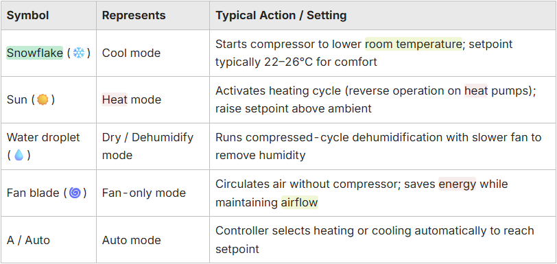
What Does the Snowflake Symbol Represent on an AC Remote?
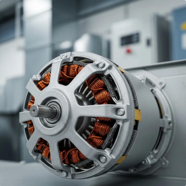
The snowflake symbol denotes Cool mode, which commands the air conditioner to run the refrigeration cycle and lower indoor temperature by engaging the compressor and circulating cold refrigerant. Mechanistically, Cool mode increases the compressor duty cycle and directs refrigerant through the evaporator to absorb heat from the room, producing conditioned air at the outlet. Use Cool mode when indoor temperature is above the desired setpoint and humidity is moderate; ideal setpoints balance comfort and energy at roughly 22–26°C. Knowing this symbol helps you avoid inefficiency like set the thermostat modestly instead of extremely low targets to reduce compressor runtime and energy draw.
Recognising Snowflake → activates → compressor (semantic triple) clarifies cause and effect for new users and guides sensible operating choices. The next subsection contrasts Cool with Heat and Dry modes so you can pick the right icon for seasonal or humidity-driven needs.
How Do the Sun and Water Droplet Symbols Indicate Heat and Dry Modes?
The sun icon signals Heat mode, which reverses the refrigeration cycle on heat-pump systems or triggers electric/gas elements on conventional units to raise indoor temperature and maintain a higher setpoint. Heat mode works by transferring heat into the room rather than removing it, and the sun → indicates → heating function relationship helps users choose the appropriate icon in colder conditions. The droplet icon indicates Dry or Dehumidify mode; it modulates compressor cycling and reduces fan speed to condense and remove moisture from the air without aggressively lowering temperature.
Practically, choose Sun for active warming and droplet for humid, muggy days when moisture (not temperature) is the primary discomfort. Understanding these distinctions prepares you for advanced functions like eco and auto modes that combine temperature and humidity goals.
How Can You Understand Advanced Air Conditioner Mode Symbols?

Advanced AC mode symbols communicate features that fine-tune comfort, timing, and airflow distribution such as sleep, timer, swing, turbo, and eco among them. Each icon implies a trade-off between speed, comfort, and energy use. These modes control mechanisms such as gradual setpoint drift in sleep mode, scheduled on/off in timer, and louver actuation in swing, delivering benefits like overnight efficiency, automated operation, and improved air distribution. Below is a focused comparison table describing each advanced symbol, its function, and energy impact so you can decide which icon to use in specific situations.

Reduces compressor cycles for efficiency; may increase runtime slightly but lowers energy consumption overall
This comparison helps you balance comfort and cost: use Turbo for rapid change, Eco for sustained efficiency, and Sleep to harmonise overnight comfort with lower energy use. Next, short lists summarise practical use cases and settings to implement these modes correctly.
- The Sleep icon improves overnight comfort while trimming energy use.
- The Timer icon ensures the system runs only when needed and avoids wasted runtime.
- The Eco icon reduces compressor duty cycles to lower electricity consumption.
Understanding advanced icons helps you tailor operation to daily routines and seasonal needs. The following H3 subsections break down functions and energy trade-offs with actionable tips for each symbol.
What Are the Functions of Sleep, Timer, and Swing Symbols on AC Remotes?
Sleep mode gently shifts setpoint and fan behavior over several hours to match nighttime comfort and reduce compressor cycles, improving sleep comfort and lowering energy use. Timer symbols let you program delayed on/off events, useful for pre-cooling before arrival or shutting the unit after you leave and they prevent unnecessary runtime that wastes energy. Swing controls actuate the louvers or swing function to distribute air more evenly; while swing has minimal direct energy impact, it reduces hot/cold spots and can allow a slightly higher setpoint for the same perceived comfort.
Practical steps: enable Sleep before bed with a moderate setpoint drift; program Timer for predictable occupancy patterns; use Swing to avoid localised drafts. These behaviors illustrate the semantic triple: Sleep mode → reduces → compressor cycling, which links mode to energy effect.
How Do Turbo and Eco Mode Symbols Improve AC Performance and Energy Efficiency?
Turbo (or powerful) mode temporarily increases compressor speed and fan output to achieve rapid cooling or heating; use it for short bursts like cooling a hot room before guests arrive, but avoid long durations because Turbo consumes significantly more power. Eco or Energy Saver mode adjusts compressor cycles and fan behavior to minimise wattage draw and often allows a slightly wider temperature tolerance to save electricity. The choice is a trade-off: Turbo delivers fast comfort at high cost, while Eco provides steady comfort at lower long-term expense.
Recommended approach: reserve Turbo for short-term needs and prefer Eco for daily operation, especially when occupancy patterns are regular. Combining Eco with Power-saving habits (closed blinds, ceiling fans) multiplies energy savings without sacrificing comfort.
What Do Air Conditioner Display Symbols Indicate About Operation and Settings?
Air conditioner indoor displays show current operation and status through numeric temperature readouts, fan speed bars or letters, mode LEDs, and error/warning icons; these indicators describe both user-selected settings and real-time system behavior. Numeric readouts communicate the active setpoint or measured room temperature, while fan bars indicate discrete speed levels or automatic modulation; together they form a readable snapshot of system state. Display icons like defrost, filter, or water-full provide maintenance and safety signals that require user attention or immediate action to avoid damage. The next paragraphs explain how to interpret temperature/fan displays and common warning/error symbols you might see on panels.
A clear understanding of display semantics reduces unnecessary service calls and helps you act swiftly when the unit signals an issue.
How Are Temperature and Fan Speed Displayed on AC Panels?
Temperature displays typically show the setpoint when the unit is idle or the actual room temperature during active operation; many models toggle between the two or include a small label to indicate which value is shown. Fan speed is often visualised as vertical bars, numeric levels, or letter codes (L/M/H for low/medium/high), and some inverters show an "auto" indicator when the unit modulates fan speed to meet load efficiently. Interpreting these displays lets you confirm whether a user input on the remote has been applied and whether the unit is in a steady control state or actively working to change conditions.
If the display shows unexpected values, use stepwise checks like confirm remote mode, verify setpoint, and watch fan indicator behavior to identify whether control inputs or a sensor reading requires adjustment. Understanding these numeric and bar displays prepares you to recognise true warnings versus normal transitional states.
What Do Warning and Error Symbols Mean on Your Air Conditioner Display?
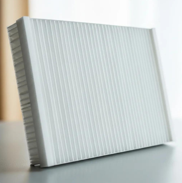
Warning symbols and error codes signal issues ranging from simple maintenance needs to component faults: common indicators include filter replacement prompts, water-full or drainage warnings, defrost mode on heat pumps, and communication or sensor error codes that require diagnostic attention. Immediate user actions often include cleaning the filter, checking drain pans and pathways, or power-cycling the unit for transient communication faults, while persistent error codes usually need professional diagnosis. Recognising whether an icon indicates a routine maintenance task or a potential compressor/PCB fault determines whether you can safely delay service or should escalate immediately.
The next section provides a compact troubleshooting EAV table and step-by-step actions to help you decide when to reset, clean, or call a technician.
How Do Air Conditioner Symbols Help Optimise Your AC Usage?
Symbols are not just labels; they are actionable signals that guide efficient operation and proactive maintenance, enabling optimised comfort with lower operating costs and extended equipment life. Icons for Eco, Auto, Sleep, and fan-only modes tell you which configuration favors energy savings versus rapid comfort, and filter or water indicators prompt timely cleaning that preserves heat-exchange efficiency. By combining symbol-informed choices such as using Eco mode during daytime and Sleep at night, you can create routines that reduce compressor stress and elongate service intervals. The advice below helps you pair symbols into efficient setups and lists simple maintenance behaviors tied to display alerts.
- Use Eco and Auto modes during stable occupancy to reduce energy consumption without manual adjustments.
- Employ Sleep mode overnight to gradually adjust setpoints and minimise compressor cycling.
- Choose Fan-only for gentle circulation during mild conditions to avoid turning on the compressor.
Adopting these symbol-based habits systematically improves efficiency and comfort, and the next subsection describes which symbols mark energy-saving and comfort modes.
Which Symbols Indicate Energy-Saving and Comfort Modes?
Energy-saving symbols typically include the leaf (Eco) and Auto indicators, while comfort-focused symbols include Sleep and Turbo for rapid changes. Eco mode reduces compressor duty and may slightly widen temperature deadbands to save energy, Auto balances heating/cooling and fan speed for efficiency, and Sleep adjusts setpoints gradually to match nighttime comfort while lowering power draw. Fan-only is a low-energy option when ventilation rather than temperature change is the objective.
For best results, pair Eco with moderate setpoints, use Auto during variable conditions, and save Turbo for brief recovery periods. Recognising these icons lets you implement routines that keep bills lower without sacrificing perceived comfort.
How Can Understanding Symbols Improve AC Maintenance and Longevity?
Display alerts such as filter change icons or water/full indicators correlate directly to maintenance tasks that preserve heat-exchange efficiency and prevent moisture-related damage. Responding promptly to filter indicators by cleaning or replacing filters restores airflow and reduces compressor load, while addressing drain warnings prevents water overflow and microbial growth. Regularly monitoring display error codes and acting on minor alerts early prevents progression into component failure, aligning short-term fixes with long-term reliability.
Schedule simple periodic checks when filter or maintenance icons appear and escalate persistent error codes to a technician; this symbol-driven maintenance rhythm lengthens service life and reduces emergency repairs.
What Are the Most Common Troubleshooting Symbols on Air Conditioners?
Troubleshooting symbols identify issues like filter blockage, water accumulation, communication faults, and compressor lockouts, and each icon implies a likely cause plus an immediate action. By linking each display symbol to a probable source and a stepwise remedial action, users can safely perform basic troubleshooting or decide to call a professional when alerts indicate safety or major component faults. Below is a practical at-a-glance EAV table that maps common display symbols and error codes to likely meanings and immediate user actions to help you triage problems quickly.

This table provides immediate actions to try safely and clarifies when icons indicate routine maintenance versus hardware issues. After trying simple resets and cleaning steps, escalate persistent or safety-related errors to professional service.
If you need help interpreting persistent error codes or prefer a qualified diagnosis, Oz Air group can assist with targeted inspection and repair.
How to Identify and Respond to Warning Symbols on Your AC Remote or Display?
Begin troubleshooting by identifying the exact symbol and cross-referencing the user manual or the EAV table above; this clarifies whether the alert is maintenance-related or safety-critical. For maintenance icons such as filter or water indicators, perform the recommended cleaning or drain checks and then observe whether the symbol clears after a power cycle. For communication or compressor-protection codes, attempt a single power-cycle and document recurring codes; repeated occurrences suggest electrical, sensor, or compressor issues that require professional diagnostics. Always prioritise safety especially if an icon indicates overheating, burning smells, or repeated compressor trips, cease operation immediately and contact professional support.
These steps move from simple user-level fixes to escalation criteria, ensuring you take efficient, safe actions before involving a technician. The next subsection explains clear thresholds for when to call a professional based on symbol behavior.
When Should You Contact a Professional Based on AC Symbol Alerts?
Contact a professional when error codes persist after basic resets, when compressor or electrical fault indicators appear, or when safety-related symbols accompany unusual noises, odors, or system shutdowns. Non-urgent maintenance prompts like filter reminders or temporary water warnings can be addressed by the user in the short term, but recurring maintenance alerts or unresolved drainage problems should be scheduled for inspection. Urgent situations include compressor overload, refrigerant leaks (indicated indirectly by persistent poor cooling plus error codes), or fault codes specifically referencing indoor-outdoor communication failure that cannot be cleared by power cycling.
Document the symbol, any error codes displayed, and the sequence of user actions taken to help the technician diagnose faster. If you need help with diagnosis or repair of persistent or safety-related alerts, Oz Air group offers assessment and service options.
Where Can You Find a Complete List of Air Conditioner Symbols and Their Meanings?
Authoritative sources for comprehensive symbol lists include your unit’s manufacturer manual, official support pages, and industry-standard documentation for HVAC controls; these model-specific resources are the best place to confirm icon variants and error-code definitions. Manufacturer manuals are especially important because some brands use custom icons or unique error-code numbering that differs from universal conventions. When manuals are unclear, technical service bulletins and industry association guidance provide standardised interpretations that clarify symbol semantics and troubleshooting protocols. The short paragraph below explains how Oz Air group can support interpretation and directs readers toward practical resources for model-specific icon translation.
How Does Oz Air Group Provide Expert Guidance on AC Symbols?
Oz Air group provides expert interpretation of both common and model-specific AC symbols by combining knowledge of HVAC controls with diagnostic procedures that map icons to underlying causes. When a display shows a maintenance or fault icon, Oz Air group's technicians can interpret error codes, perform targeted inspections, and recommend either a user-level action or a scheduled repair based on observed symptoms. This service helps eliminate guesswork, prevents unnecessary parts replacement, and prioritises safety when symbols indicate potential hazards. If you require interpretation or on-site diagnosis for persistent or unclear icons, reach out to request professional assessment from Oz Air group.
What Resources and Manuals Support Accurate Symbol Interpretation?
The most reliable resources are the unit manufacturer’s user and service manuals, official technical bulletins, and accredited HVAC training materials that document iconography and error-code semantics for specific models. When manuals are unavailable, conservatively compare the displayed symbol to universal icon sets and then verify with a technician or official support channel to avoid misdiagnosis. For model-specific searches, note the exact model number and any error codes shown so resources and technicians can quickly match symbol definitions to board-level or sensor issues.
Maintaining access to manufacturer documentation and logging symbol occurrences reduces downtime and supports targeted maintenance that preserves equipment longevity. For professional help interpreting symbols and planning corrective actions, consider contacting Oz Air group for a diagnostic consultation.

Areas we service
Oz Air covers Melbourne and its northern suburbs.

Get in touch


.png)