


.png)

What is a Printed Circuit Board (PCB) in an Air Conditioner?


Government Rebates Now Available on Energy-Efficient Air Conditioners when Replacing your Gas Heater.
A printed circuit board, or PCB, in an air conditioner is the electronic control board that picks up inputs, runs the control logic, and switches power to things like compressors, fans, and safety devices. This guide explains how an AC PCB works, what bits and pieces make it up, common ways they can fail, and some handy diagnostic steps. This way, homeowners and technicians can spot problems early on. Many system faults that might seem mechanical actually start with control board errors, so getting your head around the PCB’s role really helps avoid chucking out good parts and keeps your system running smoothly. This article maps out the signal flow from your thermostat to the compressor, lists the main PCB components and what happens when they play up, outlines testing and a decision guide for whether to repair or replace, and shows you routine maintenance and protection steps. Later sections describe how we at Oz Air Group approach PCB diagnostics and how to schedule a professional inspection if you'd prefer a certified technician to handle the electrical testing. Throughout, we've used keywords like printed circuit board, PCB, air conditioning PCB, and AC control board to help you match symptoms to likely control board issues quickly.
What is a Printed Circuit Board in an Air Conditioner?
A printed circuit board in an air conditioner is the central electronic module that links sensors, user controls, and power outputs to manage heating and cooling cycles. It converts low voltage thermostat or sensor inputs into switched outputs for contactors, fan motors, and compressor start circuits, while enforcing safety interlocks like delay timers and overload protections. The PCB therefore acts as both a logic controller and a power distribution interface, so a fault can produce symptoms ranging from a complete no start to intermittent operation. Understanding this control role clarifies why error codes, unexpected cycling, or single component failures often trace back to PCB faults. The next subsection explains the signal flow mechanisms the PCB uses to translate user commands into mechanical action.
How does a PCB control air conditioning functions?
A PCB controls air conditioning functions by reading inputs, such as from thermostats, temperature sensors, and pressure switches, and actuating outputs, like relays, contactors, and motor drivers, according to built in logic and timing. Sensors provide electrical signals that the PCB’s microcontroller or control IC interprets. That logic then energises relay coils or solid state drivers to start compressors or fans. Safety timers prevent rapid short cycling. For example, when the thermostat calls for cooling, the PCB delays compressor engagement until safeguards pass and then energises the contactor coil while monitoring current draw for overloads. This input, processing, output pattern ensures coordinated operation and protects equipment. A simple three step signal flow highlights the core process:
- Sense: The PCB receives signals from the thermostat and onboard sensors.
- Decide: The control logic evaluates conditions and safety criteria.
- Act: Relays or drivers switch power to the compressor and fans.
These steps explain why our technicians begin troubleshooting with sensor readings and relay activation checks before replacing large components.
What are the main components of an air conditioning PCB?
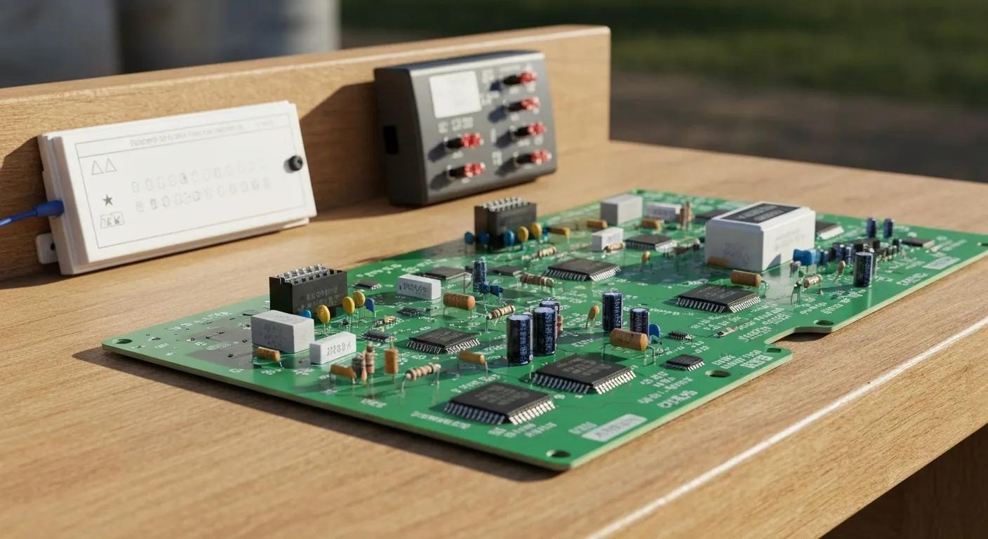
The main components on an air conditioning PCB include the microcontroller or control IC, relays or contactor drivers, electrolytic and film capacitors, power transformer, fuses, connectors, and various sensors and signal conditioning parts. Each part contributes a distinct function: the microcontroller runs control logic, relays switch high power circuits, capacitors stabilise voltages, and connectors provide mechanical and electrical interfaces to the rest of the system. Below is a compact table that maps common components to their functions and the impact a failure has on AC operation.
The table below helps map visible PCB parts to likely system effects so our technicians and informed homeowners can prioritise tests.
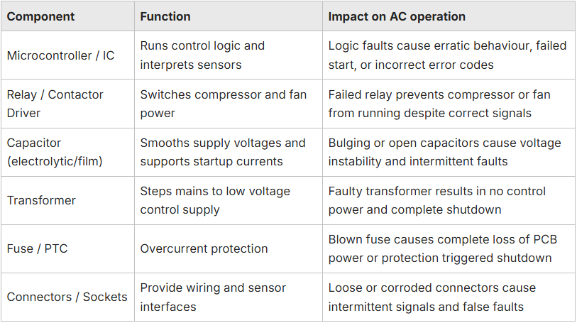
Mapping component to function to impact allows quicker isolation of fault sources and informs whether targeted component replacement or full board replacement is appropriate. The following section explains why the PCB’s condition matters for overall performance.
Why is the PCB Important for Air Conditioner Performance?
The PCB is critical because it coordinates timing, safety, and efficiency across the entire HVAC system, directly influencing comfort, energy use, and equipment longevity. When the PCB executes logic correctly, compressors and fans run at the right times with appropriate delays, avoiding short cycling that reduces efficiency and causes wear. Accurate sensor interpretation by the PCB prevents false faults and enables efficient modulation of system operation, while integrated safety routines protect major components from overloads. Because of these roles, a degraded PCB can increase energy consumption, cause uneven temperature control, and lead to secondary component stress that shortens system life. The next subsection details how specific PCB faults translate into operational problems.
How does a faulty PCB affect air conditioning operation?
A faulty PCB can produce a wide range of operational issues such as failure to start, intermittent operation, incorrect fan or compressor sequencing, or persistent error codes that mask root causes. For instance, a PCB that fails to energise the compressor contactor will result in the fan running without cooling, while a relay that sticks can cause continuous compressor operation and overheating. Intermittent faults often stem from cracked solder joints, corroded connectors, or failing capacitors, which create unreliable signal paths and unpredictable behaviour. These operational failures not only reduce comfort but can escalate into mechanical damage, prompting more costly repairs if left unchecked. Homeowners noticing these symptoms should follow safe basic checks before escalation.
What are the benefits of a properly maintained PCB in AC units?
A properly maintained PCB improves reliability, reduces emergency repairs, and helps sustain energy efficient operation by ensuring accurate control and early fault detection. Regularly protected and inspected control boards reduce the risk of surge related failures and corrosion, which translates into fewer unscheduled service calls and lower lifetime maintenance costs. Proper maintenance also preserves fault logging capabilities and diagnostic output, enabling our technicians to find problems faster and repair them with minimal parts swapping. Ultimately, a cared for PCB contributes to consistent comfort and predictable operating costs, so preventive measures like surge protection and periodic inspections are cost effective investments. The next section outlines practical diagnostic and repair workflows used by our trained technicians.
How Does Oz Air Group Diagnose and Repair PCB Issues in Air Conditioners?
PCB diagnostics begin with a structured inspection that combines visual checks, safe power isolation, electrical measurements, and functional tests to identify root causes efficiently. Our technicians first look for visible damage, things like burn marks, swollen capacitors, loose connectors, and signs of moisture. Then they measure low voltage supply presence, relay coil voltages, and continuity of fuses. Functional tests follow, where relays are actuated and outputs monitored while the system is run under controlled conditions. Bench testing of suspect boards can isolate faults away from the unit. This stepwise approach reduces unnecessary replacements by diagnosing whether a board level repair, component swap, or full replacement is appropriate. After diagnostics, our technicians document findings and consult the customer with options based on safety and cost considerations.
At Oz Air Group, the diagnostic workflow uses calibrated meters, safe isolation practices, and bench testing rigs to verify failures before recommending repair or replacement. Our technicians follow transparent decision criteria. If a single discrete component failure is identified and safe parts are obtainable, targeted repair is preferred. If multiple board areas show heat damage or corrosion, the recommended action is replacement. To schedule a diagnostic inspection, contact Oz Air Group and request a PCB diagnostic. A technician will confirm available times and describe the inspection process. This service first explanation helps customers understand the recommended next steps and expected diagnostic timeline.
The following table summarises common tests, what they check, and the pass or fail indicators that guide next steps.

These tests form a repeatable decision tree that limits guesswork and aligns repair actions with safety and cost objectives. The following subsection provides a clear repair versus replace decision guide.
What testing methods does Oz Air use for PCB troubleshooting?
Our Oz Air Group technicians apply a consistent set of tests: visual inspection, low voltage and mains voltage checks, continuity and fuse verification, relay activation checks, and bench functional testing where safe and appropriate. Visual inspection establishes immediate evidence of thermal damage or corrosion, while meter based voltage and continuity checks confirm whether control supplies and traces are intact. Relay and output activation tests verify the board’s ability to switch external loads, and bench tests simulate control conditions to reproduce faults without risking other system components. Each test narrows the fault hypothesis and defines whether a targeted component repair is feasible or whether the board shows systemic damage that warrants replacement.
The earlier table summarised these tests. Our technicians use results to recommend repair, replacement, or further component sourcing. After testing, the repair versus replace decision guide provides specific guidance based on condition and cost.
When should a PCB be repaired versus replaced?
Deciding to repair or replace a PCB depends on the extent of damage, availability and cost of replacement parts, safety considerations, and whether firmware or design obsolescence is a factor. Generally, repair is justified when a single or small number of discrete components have failed, for example, one capacitor or a relay, and replacements are reliable, safe, and cost effective. Replacement is recommended when multiple components are heat damaged, trace corrosion is present, connectors are compromised, or the board contains integrated circuits that cannot be reliably serviced. The table below provides a concise decision guide mapping conditions to recommended actions.

Use these criteria alongside safety and warranty considerations. When in doubt, professional advice reduces the risk of repeat failures or unsafe repairs. The next H2 lists common PCB problems and their root causes.
What Are Common PCB Problems in Air Conditioning Systems?
Common PCB problems include power surge damage, moisture related corrosion, overheating, and mechanical shock or vibration that fractures solder joints. Each of these produces distinct symptoms homeowners can recognise. Surge damage often destroys capacitors or ICs and can present as a sudden total failure after a storm, while moisture and corrosion lead to intermittent faults, discoloured traces, and connector failures. Thermal stress from restricted airflow or high ambient temperatures accelerates component aging, leading to swollen capacitors and degraded solder joints. Mechanical shocks from transport or impact can create cracked solder joints that produce intermittent symptoms. Recognising these root causes helps prioritise preventive steps and informs whether targeted repairs will be reliable.
Below is a concise list of frequent PCB failure modes with one line symptom mappings to help homeowners triage issues before calling a technician.
- Power surge damage: Sudden total board failure or blown fuses after electrical events.
- Moisture and corrosion: Intermittent operation, error codes, and visible greenish corrosion around connectors.
- Overheating / thermal stress: Gradual performance loss, swollen capacitors, and increased error frequency.
- Mechanical shock / vibration: Intermittent faults that change when the unit is tapped or moved.
- Connector or wiring faults: Erratic signals and component misbehaviour despite healthy board components.
This prioritised symptom list helps homeowners perform safe initial checks, such as verifying breakers and power supply, before requesting professional service, which reduces unnecessary service calls. The next two subsections explain environmental causes and how to identify failure signs.
How do power surges and environmental factors damage PCBs?
Power surges damage PCBs by overvolting capacitors, semiconductors, and ICs, resulting in burnt traces, latent component weakness, or immediate failure. Moisture ingress promotes corrosion of solder joints and connector pins, creating high resistance paths that cause intermittent signals and localised heating. Elevated ambient temperatures or blocked ventilation increase thermal cycling stress, accelerating electrolyte breakdown in capacitors and weakening solder joints over time. Preventive measures include installing surge protection, ensuring adequate ventilation, and sealing control enclosures to limit moisture exposure. These protections form part of a broader maintenance plan to reduce PCB related failures.
Introduction to Printed Circuit Board Failures: Environmental and Manufacturing Etiologies
The low rate failure modes discussed can originate from both environmental stresses and manufacturing process issues, including defects associated with printed circuit boards. The progression of these defects into low rate failure modes can be a gradual process.
Introduction to printed circuit board failures, 2009
What signs indicate PCB failure in an air conditioner?
Signs of PCB failure include no power to controls, continuous error codes, fan only operation without cooling, strange smells like burnt electronics, and visible damage such as charred components. Homeowners can perform quick safe checks: confirm mains power and circuit breakers, reset the system per manufacturer guidance, and observe whether error codes persist. If issues remain, further electrical testing by a qualified technician is necessary. Because PCB faults can mimic sensor or compressor issues, stopping and calling a professional when electrical symptoms appear prevents misdiagnosis and unnecessary mechanical replacement. The following section details maintenance and protection approaches to extend PCB life.
Predicting Printed Circuit Board Failure Under Humidity: Climatic Reliability of Electronic Components
Humidity induced corrosion failures in electronic devices are a significant factor contributing to robustness and reliability challenges. These issues stem from a combination of external and inherent factors. External factors include the widespread adoption of electronics, exposing them to diverse climatic conditions. Inherent factors encompass the use of multiple materials, miniaturisation trends, and contributions from manufacturing processes.
Climatic Reliability of Electronics: Prediction of PCB Failure under Humidity using Predictive Analytics, S Bahrebar, 2022
How Can You Maintain and Protect the PCB in Your Air Conditioner?
Regular maintenance reduces PCB stress and extends service life by preventing moisture ingress, minimising thermal load, and protecting against surges. Routine tasks include cleaning filters and coils to improve airflow, visually inspecting control enclosures for moisture or pests, and checking that connectors are secure and free of corrosion. Environmental protections such as surge protection devices, sealed control housings, and ensuring correct electrical grounding substantially lower the probability of catastrophic board failure. Additionally, professional electrical inspections at scheduled intervals catch early signs of component aging that a homeowner may miss. The next subsection provides a checklist of routine checks homeowners and service technicians should perform.
What routine checks help prevent PCB damage?
Implementing a simple inspection routine can catch early issues before they escalate into PCB failures. Homeowners should clean or replace air filters regularly, ensure outdoor units have unobstructed airflow, and visually inspect the control box for moisture, pests, or corrosion. A qualified technician should periodically measure control supply voltages, test surge protection, and verify that connectors and harnesses are securely seated. These electrical checks require proper isolation and meter skills. Performing these checks quarterly to biannually, depending on the environment, reduces thermal stress and corrosion risk. The checklist below summarises key routine actions.
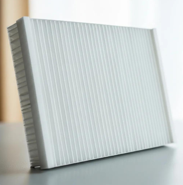
- Check airflow and clean filters: Maintain proper ventilation to prevent overheating.
- Inspect control enclosure for moisture: Seal or repair any ingress points promptly.
- Verify secure connectors and wiring: Tight connections reduce intermittent faults.
- Test surge protection and supply voltages: Ensure stable control power and protection.
Regular basic home maintenance combined with professional electrical checks reduces PCB failure probability and supports reliable, efficient operation. The next subsection explains how proper installation extends PCB life.
How does proper installation and usage extend PCB life?
Correct installation, including proper grounding, correct fuse sizing, secure mounting, and avoiding excessive vibration, reduces mechanical and electrical stress on PCB components. Ensuring the control board is mounted in a sheltered enclosure with adequate ventilation limits thermal cycling and ingress of dust or moisture, which are common drivers of premature failure. Appropriate wire routing and secure connector use prevent chafing and intermittent connections that mimic board faults, and installing surge protection at the electrical service point mitigates transient overvoltages. Professional installers follow manufacturer wiring diagrams and torque specifications to reduce the risk of installation related failures, making professional service a valuable investment for longevity.
Where Can You Get Professional PCB Service for Air Conditioners from Oz Air Group?
Oz Air Group offers professional PCB inspection, diagnostic testing, and repair or replacement services delivered through our trained technicians using standard electrical diagnostic tools and bench testing procedures. Customers can expect a structured inspection, transparent reporting of findings, and recommendations that prioritise safety and cost effective outcomes. We at Oz Air Group emphasise clear communication about whether a targeted component repair or full PCB replacement is the safer long term choice and schedule follow up work based on parts availability. To arrange service, contact Oz Air Group and request a PCB inspection. A technician will outline the inspection scope and expected timelines.
Intro to service list: The steps below describe what to prepare and what to expect when scheduling a PCB inspection or repair with Oz Air Group.
- Provide unit details and symptoms: Have the make and model, plus a description of observed faults, ready when you contact Oz Air Group.
- Agree on an an inspection window: Our technicians will confirm availability and any pre visit safety instructions.
- Receive a diagnostic report: After inspection, Oz Air Group will explain findings and present repair or replacement options.
- Schedule agreed repairs: If parts are required, the technician will estimate lead times and return visits.
This straightforward process ensures customers understand the inspection results and the recommended path forward, whether that is targeted repair or full PCB replacement. The last subsection explains reliability features customers can expect from Oz Air Group’s PCB service.
What makes Oz Air Group’s PCB repair service reliable?
From our perspective at Oz Air Group, reliability stems from disciplined diagnostics, use of calibrated testing equipment, and a decision process that prefers safe, documented repairs. Our technicians document visual and electrical test results, validate repairs via bench and in situ functional testing, and communicate trade offs between component level fixes and full board replacement. Service reliability also includes transparent timelines for sourcing components and a clear explanation of the expected reliability of repairs versus replacements. By focusing on diagnostic clarity and safe testing practices, we at Oz Air Group aim to reduce repeat visits and deliver predictable, durable outcomes.
How to schedule a PCB inspection or repair with Oz Air Group?
To schedule a PCB inspection or repair, contact Oz Air Group and provide basic information about your equipment and symptoms so our team can prepare the appropriate diagnostic tools. Be ready to share the unit model, observed error codes or behaviours, and convenient appointment windows. This helps the technician determine if bench testing or on site repairs are likely. Typical inspection visits include visual checks, voltage and continuity tests, and functional verification. If parts are needed, Oz Air Group will provide estimated lead times and a cost recommendation. Request service through Oz Air Group to arrange a diagnostic visit and receive a transparent report with recommended next steps.
Preparing basic unit information and symptoms accelerates diagnosis and improves the accuracy of repair recommendations.
- Have unit model and symptom description ready: This helps Oz Air Group prepare the correct diagnostic approach.
- Note any recent power events or environmental exposures: Mentioning surges or water ingress informs prioritisation.
- Expect a diagnostic report and recommendation: Oz Air Group provides clear options and timelines after testing.
Scheduling a professional PCB inspection through Oz Air Group streamlines diagnosis and connects customers to trained technicians who follow structured testing and reporting, allowing safe, cost effective decisions about repair or replacement.
Areas we service
Oz Air covers Melbourne and its northern suburbs.

Get in touch


.png)