


.png)

What Is a Thermistor on an Air Conditioner?


Government Rebates Now Available on Energy-Efficient Air Conditioners when Replacing your Gas Heater.
A thermistor is a small, temperature-sensitive resistor used inside air conditioners to measure temperature and feed that information to the control board. That feedback helps the system adjust cooling, protect its components, and keep your place comfy. This guide explains what an AC thermistor is, how it senses temperature, the common types and where you'll find them in your HVAC gear, warning signs they might be on the blink, practical steps for testing them with a multimeter, and some easy maintenance and replacement tips. You’ll learn how thermistor resistance changes map to temperature, how to interpret meter readings, and which everyday symptoms point to a failing sensor. We cover both the theory, NTC versus PTC resistance behaviour, and safe field procedures you can try at home, plus when to call a professional. Keywords like thermistor, AC thermistor, air conditioner thermistor, AC temperature sensor, NTC thermistor, and how to test AC thermistor are included to keep this guide searchable and useful.
Here at Ozair Group, our field technicians are out there every day diagnosing sensor issues. We always stress safe, repeatable multimeter testing and making sure any replacement sensors perfectly match the original's resistance curve and how it's mounted, not just the part number. This article really shows our hands-on way of doing things: always cut the power before you start testing, get clear measurements, and pick replacement sensors that behave just like the original when it comes to resistance versus temperature. If your own checks show readings that are a bit off or inconsistent, we reckon it's best to follow the professional steps we've laid out further down this guide.
What Is an AC Thermistor and Why Is It Important?
An AC thermistor is a compact resistive sensor whose electrical resistance changes predictably with temperature. The control board reads that resistance (or a derived voltage) and uses it to control system operation. Thermistors measure temperature at specific spots, like room air, the evaporator coil, or the outdoor condenser, and translate that into data the PCB uses for functions like maintaining setpoint, preventing coil freeze, and modulating inverter compressors. Accurate sensing keeps everyone comfortable, minimises unnecessary running time, and protects the unit's components. If it's inaccurate, you'll end up with poor temperature control and extra stress on your gear. Remember: thermistors are sensors inside the unit; thermostats are the user-facing controllers that tell the system what temperature to hold.
How thermistors report temperature to the control board explains why the choice between NTC and PTC matters depending on the sensor’s location.
How Does a Thermistor Work in an Air Conditioner? Principles of Temperature Sensing Explained
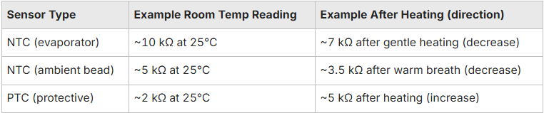
Thermistors work because their resistance changes with temperature. NTC (negative temperature coefficient) thermistors fall in resistance as temperature rises; PTC (positive temperature coefficient) thermistors rise in resistance as temperature rises. In an AC, the control board measures that resistance (or the voltage in a bias circuit) and converts it to temperature using a lookup table or calibration curve. For example, a typical bead-style NTC on an evaporator might read about 10 kΩ at 25°C and drop as the coil warms. The control logic uses these predictable curves to take action, like stopping the compressor before things freeze up, kicking off a defrost cycle on a heat pump, or tweaking the inverter speed for comfort and efficiency.
This measurement process is also why replacement sensors should match the original sensor’s resistance versus temperature curve, a point we cover again when discussing replacement choices.
What Roles Do Thermistors Play in Regulating AC Performance and Comfort?
Thermistors handle several control and protection tasks inside an air conditioner. As ambient sensors, they guide how your thermostat controls things and cycles the unit. As evaporator sensors, they stop the coil from freezing up by telling the system to ease off the cooling if it gets too chilly. On inverter systems, continuous temperature feedback from sensors enables capacity modulation, which improves efficiency and reduces short-cycling. Practical examples include an evaporator thermistor detecting a sudden temperature drop and ramping off the compressor to avoid ice, or an ambient sensor that compensates for strong solar gain to prevent overshoot.
These roles explain the symptom patterns you’ll see when a sensor fails. The next section lists common thermistor types and how their form factors match specific roles inside the unit.
What Are the Types of Thermistors Used in Air Conditioners?
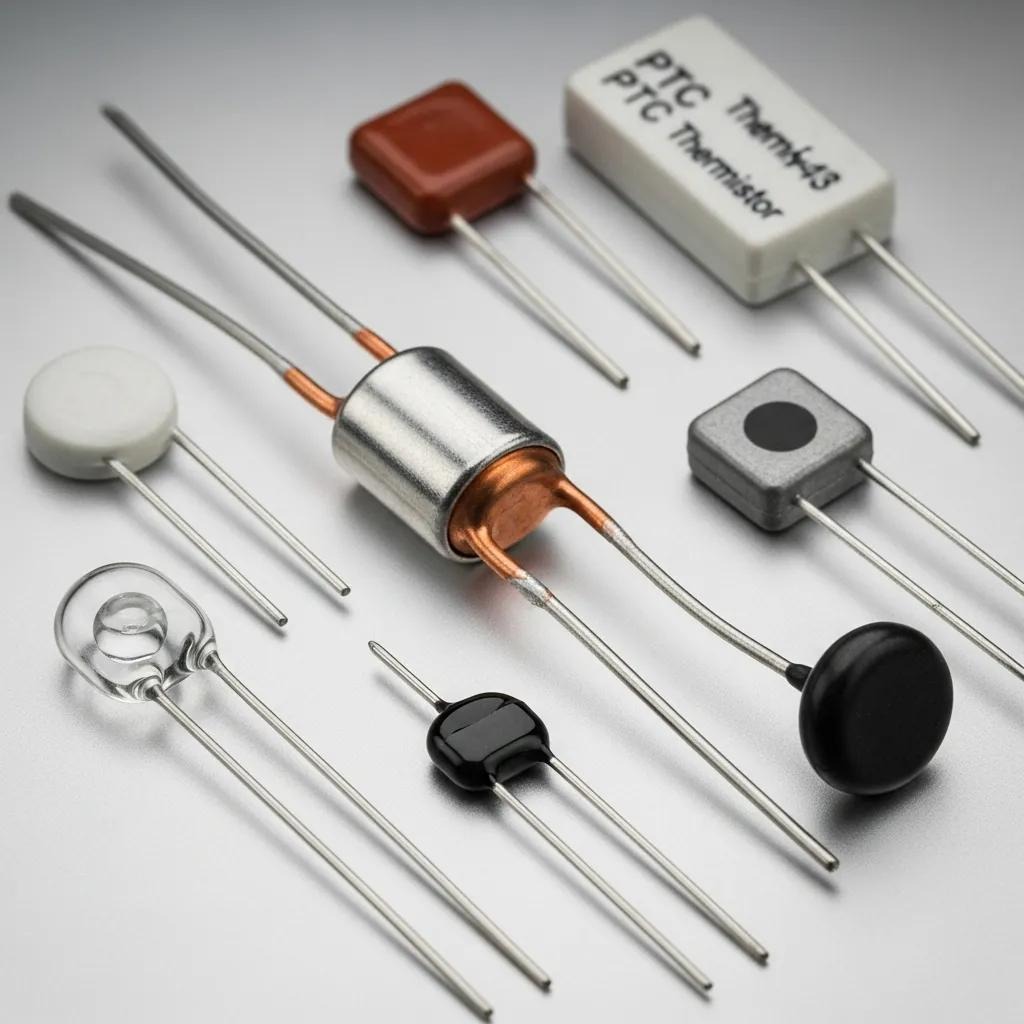
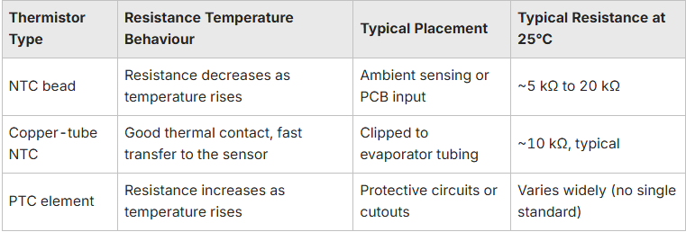
AC thermistors fall into NTC and PTC families and come in form factors like bead, tubular/copper-tube, and bonded or encapsulated assemblies. NTCs are the most common for temperature sensing because their decreasing resistance with higher temperature fits how many control boards map temperature. PTCs are often used for protective functions or cutoff logic. Form factor matters: bead thermistors respond quickly for ambient sensing, copper-tube NTCs clip to evaporator tubing for accurate coil temperature readings, and encapsulated assemblies protect the sensor in locations prone to vibration or moisture.
Below is a quick comparison to help with selection and troubleshooting.
How Do NTC and PTC Thermistors Differ in Function and Application?
NTC thermistors show a smooth, predictable drop in resistance as the temperature goes up, which makes them spot on for precise temperature measurement, like sensing the ambient air, the evaporator, or the condenser. PTC thermistors provide a rising resistance and can act like a threshold trip in protective circuits or heater control. Manufacturers usually specify NTCs for sensing because their negative slope aligns with control-board calibration tables; PTCs are selected when a clear trip point is needed. Because tolerance and curves vary by part, technicians consult the manufacturer’s resistance curve rather than relying on a single resistance value.
Knowing these differences helps place the right sensor in each location. The next subsection maps common sensor placements within the AC.
Where Are Thermistors Located Within Your AC System? Common Placement and Roles
Thermistors are installed where temperature data matters: on the evaporator coil, near the indoor air intake for room sensing, on the outdoor condenser for ambient feedback, and sometimes on compressor housings for safety monitoring. Each spot supports a specific job. For instance, evaporator thermistors protect against freezing and help manage superheat, ambient thermistors influence your comfort settings and how often the unit cycles, and condenser thermistors allow for clever head-pressure strategies on some systems. Accurate readings depend on secure mounting and clean surroundings; a loose sensor or one covered in debris will report wrong temperatures and cause control errors.
What Are the Symptoms of a Faulty AC Thermistor?
If a thermistor is on the way out, you'll usually notice symptoms like the temperature being a bit off, erratic cycling, the evaporator freezing up, or strange defrost behaviour. Early homeowner checks include visually inspecting sensor wiring and mounts, comparing thermostat display to a reliable room thermometer, and looking for ice on the evaporator. A quick triage can reduce downtime and point to whether multimeter testing is the next step. Below is a short, easy-to-scan symptom list for quick recognition.
- Temperature mismatch: Your thermostat setting doesn't quite match how the room actually feels. This is a good sign the sensor might have drifted a bit.
- Short-cycling or erratic cycling: The compressor starts and stops more often than usual due to unstable temperature feedback.
- Evaporator freezing or defrost anomalies: Ice buildup when the sensor fails to register low coil temperatures.
- Intermittent cooling: Cooling that comes and goes, often caused by loose wiring or an intermittently open sensor.
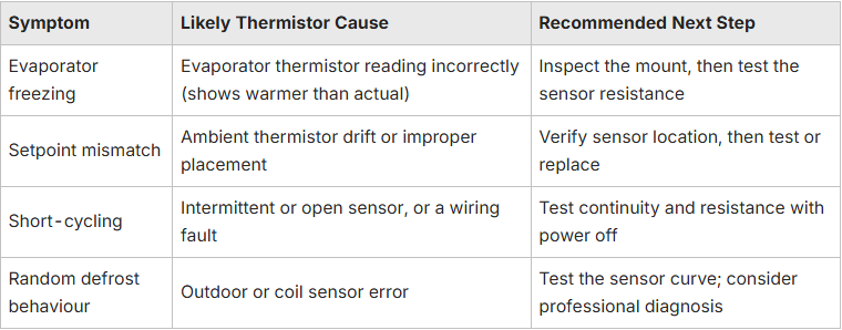
These signs point you toward which sensor to test. The table below connects common symptoms to likely thermistor causes and recommended next steps.
How Does a Faulty Thermistor Affect AC Cooling and Energy Efficiency?
A bad thermistor misleads the control board, which can make the compressor run too long or too often. If a sensor reads cooler than it actually is, your system will overcool and run for longer than needed. If it reads warmer, it can make the compressor short-cycle, meaning it starts and stops more often, which wears out the motor quicker. Even small increases in running time add up: a single extra 10-minute cycle per hour can noticeably raise seasonal energy use. Fixing sensor faults early helps preserve efficiency, reduce utility bills, and extend equipment life.
Understanding these impacts motivates timely testing and repair. The following checklist helps homeowners spot common signs before testing.
What Are Common Signs Indicating Thermistor Malfunction in Your Air Conditioner?
Homeowners can use a quick checklist to spot thermistor issues, always keeping safety top of mind. Record discrepancies between the thermostat and a calibrated room thermometer, look for ice on visible coil sections, note repeated error codes or blinking lights on the indoor unit, and listen for frequent compressor starts. These observations narrow down whether an ambient or coil sensor is likely at fault and prepare you for safe multimeter testing.
If the checklist points to a likely sensor issue, the next section provides Ozair Group’s step-by-step multimeter testing procedure to verify and interpret thermistor resistance readings.
How to Test an AC Thermistor Using a Multimeter: Ozair Group's Step-by-Step Guide
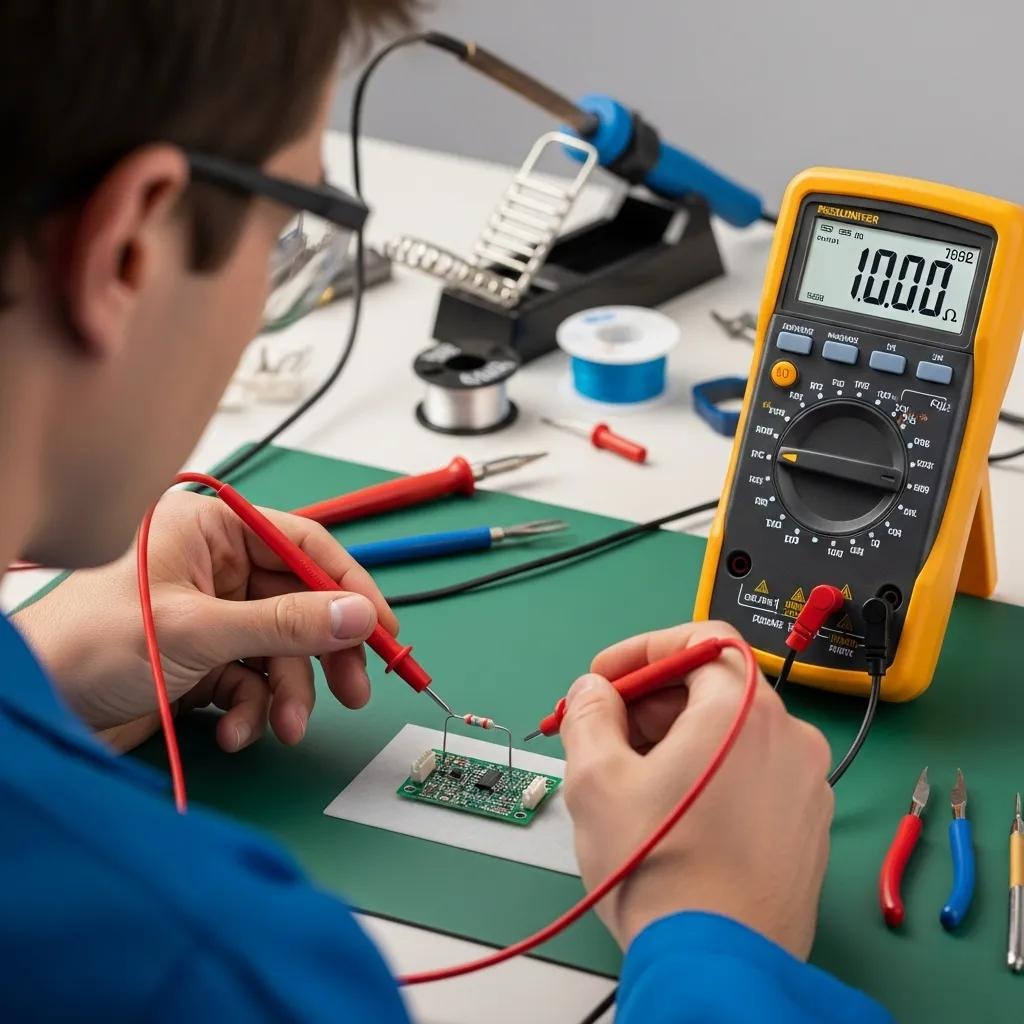
Safe, reliable thermistor testing always kicks off by isolating the power and using a decent digital multimeter set to measure resistance (ohms). Here at Ozair Group, our technicians always double check there's no mains voltage before they even think about touching sensor leads. The basic flow: remove power, access the sensor leads at the PCB or harness, record baseline resistance at room temperature, apply gentle heat (warm breath or a low-setting heat gun), and confirm the resistance moves in the expected direction for NTC or PTC sensors. Proper interpretation compares the measured direction and magnitude of change to the sensor’s expected curve: NTC resistance falls with heat, PTC resistance rises. The numbered steps below are written for clear, practical execution.
- Turn off power to the air conditioner at the breaker and confirm zero voltage with your multimeter.
- Remove access panels and locate the thermistor leads at the PCB or sensor harness.
- Set your multimeter to an appropriate resistance range and record the baseline reading at room temperature.
- Apply controlled heat to the sensor and watch the resistance change direction and amount.
- Compare the result to the expected NTC/PTC response and manufacturer tolerance; if measurements are out of spec, plan for replacement.
These steps give a simple DIY diagnostic sequence. The technical subsections below list required tools, safety cautions, and sample measurements to help you interpret results accurately. If your DIY testing uncovers big discrepancies or wiring damage, Ozair Group reckons it's best to get in touch with a technician, as we've described after these examples.
What Tools and Safety Precautions Are Needed for Thermistor Testing?
To test a thermistor safely, you'll need a trusty digital multimeter, insulated tools for getting those panels off, a small, controlled heat source (like a hair dryer or some warm water), and basic personal protective gear, things like gloves and eye protection. Key safety steps: shut off mains power and verify the absence of voltage, avoid probing live circuits, and ensure your heat source won’t damage sensor insulation or wiring. Use insulated screwdrivers for access panels and don’t test thermistors with power applied unless you’re trained and following a verified live-voltage procedure. Observing these precautions reduces the risk of shorting, component damage, or injury.
How to Measure Thermistor Resistance and Interpret Results Accurately?
Measure the baseline resistance at a known room temperature and log the reading. Then warm the sensor slightly and note whether resistance moves in the expected direction: an NTC should decrease, a PTC should increase. Use typical values and tolerances as guidance rather than relying on a single number. If the thermistor shows no change, is open circuit, or reads far outside expected tolerance, replacement is likely. Always re-check connectors and wiring before deciding the sensor is bad.
Use these examples to judge whether the sensor is following expected NTC or PTC behaviour. If readings deviate or wiring looks damaged, arrange a professional inspection.
If your DIY multimeter testing shows the thermistor is a bit out of whack, gives you dodgy readings, or uncovers wiring or PCB issues that are more than just a simple sensor swap, it's time to call in a qualified technician. Ozair Group can do advanced diagnostics, find the exact right replacement sensor for you, and make sure it's all calibrated properly with the control board. This is super important for inverter systems, where the sensor's curve really affects how the unit modulates.
How to Maintain and Replace Your AC Thermistor for Optimal Performance
Keeping your thermistors accurate really starts with looking after your system regularly: clean or replace your filters, keep those coils free of gunk, make sure sensor mountings are secure, and try not to stress the sensor leads when you're doing any service. Regular visual checks during seasonal maintenance help spot frayed wires, loose clips, or corroded connectors that cause intermittent faults. When replacing a thermistor, match the resistance curve (NTC vs PTC), the physical form factor (bead, copper-tube), and the mounting style to the original so the control board remains calibrated. Recording baseline resistance at installation makes future troubleshooting easier and confirms proper operation.
Here’s a short checklist of preventive steps to keep sensors reliable and the system efficient.
- Keep coils clean: Dirty evaporator or condenser coils can insulate sensors and cause false readings.
- Change filters regularly: Clogged filters change airflow and affect sensor exposure.
- Inspect sensor mounts and wiring: Tighten loose clips and repair damaged insulation or connectors.
- Avoid direct heat on sensors during service: Excessive heat can alter calibration or damage encapsulation.
What Maintenance Practices Support Thermistor Longevity and AC Efficiency?
Protecting the sensing environment and wiring is the best way to preserve thermistor accuracy: keep coils and filters clean to avoid hotspots, secure sensors against vibration and moisture, and check connector tightness and corrosion during seasonal inspections. On inverter systems, route sensor wiring away from high-current runs to reduce electromagnetic interference that can corrupt readings. Annual professional inspections help catch subtle drift before it affects comfort or efficiency.
Routine care keeps sensor readings within manufacturer tolerance, simplifying future diagnostics and replacements.
When and Why Should You Replace a Faulty Thermistor in Your Air Conditioner?
Replace a thermistor when multimeter tests show an open circuit, no response to temperature, readings far outside expected tolerance, or persistent intermittent behaviour despite solid wiring. Also replace it if you see any visible damage, like cracked encapsulation, corroded leads, or broken mounting clips. When choosing a replacement, match the sensor’s resistance at 25°C and its resistance versus temperature curve to the original; a sensor with the wrong curve can cause lasting control issues. If replacement requires PCB-level access or difficult wiring work, hire a professional to ensure correct installation and calibration.
If your testing gives you inconsistent readings, if you're suss on wiring or PCB faults, or if you just prefer a professional to handle it, then schedule a diagnostic inspection. Ozair Group can help you find the right sensor and make sure your system is running perfectly after it's replaced.

Areas we service
Oz Air covers Melbourne and its northern suburbs.

Get in touch


.png)